raspirobotboard3
Python library and design files for the RasPi Robot Board V3
If you were looking for the library for the version 2 board go to https://github.com/simonmonk/raspirobotboard2
Installing the Python Libraries
The simplest way to install the library is to run the command below in a Terminal window:
$ sudo pip install rrb3
Alternatively to download and install the library manually, for example to be able to see the example files, issue the following commands
$ cd ~
$ git clone https://github.com/simonmonk/raspirobotboard3.git
$ cd raspirobotboard3/python
$ sudo python setup.py install
Attach the RRB3 to your Raspberry Pi. You do not need to attach batteries, motors or anything else to the RRB3 just yet. For now you can just power it through the Pi's normal USB power connector.
Lets run some tests from the Python Console now that everything is installed. We can experiment with the RRB3, even without any motors
Open a Python console (Python2 not 3) by typing the following into a Terminal window:
$ sudo python
Then, within the python console, type the following, one line at a time:
from rrb3 import *
rr = RRB3(9, 6)
rr.set_led1(1)
rr.set_led1(0)
rr.set_led2(1)
rr.set_led2(0)
rr.sw1_closed()
The last step should display the answer "False" because no switch is attached.
If you prefer, you can use True and False in place of 1 and 0 in the examples above.
Connect a Battery and Motors
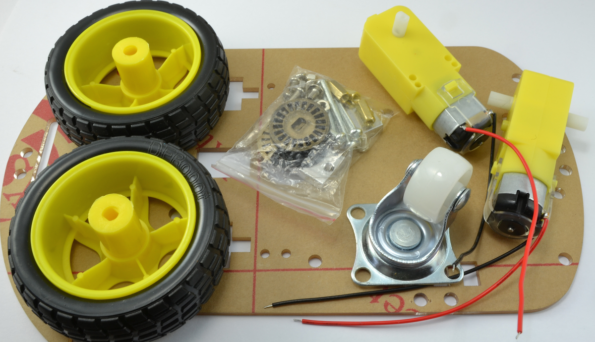
The quickest way to use the RRB3 as a roving robot is to buy a robot chassis such as the Magician Chassis (available from many sources) or similar low-cost robot chassis kits from eBay. These kits come as a laser cut body, a pair of gearmotors, often a battery box and nuts and bolts to fix it all together.
Here is one such chassis. The first step is to bolt this all together. Note that these are usually supplied with a 4 x AA battery box. You will need to swap this for a similar 6 x AA battery box or a 7.2V LiPo battery pack. Rechargeable batteries are a good idea when driving motors.
Once the chassis is built, use some of the bolts suppled to fix the Raspberry Pi on the chassis and then attach the RRB3 onto the GPIO connector. Make sure its the right way arround, and that all the pins meet up with the socket.
The leads from the motors will thread up through the chassis and each pair of leads should go to one of the two screw terminals labelled L and R for (left and right). If you put the leads in the wrong way around, the direction of the motor will be opposite to that expected, so just swap them over if this happens.
Next, make sure that your Raspberry Pi's USB power lead is unplugged. From now on we are going to power it from batteries.
If the RRB3 is powered only from your Raspberry Pi, then the motor and OC outputs will not work, but the rangefinder, LEDs and I2C interface will work. To use the Motors and OC outputs, you must connect an external power source to the RRB3.
It is a good idea to leave the wheels off the robot chassis for now so that it does not unexpectedly drive itself off your table. One or both of the motors may spin as the Raspberry Pi starts up.
Wire the battery pack into the third pair of screw terminals. +V towards the outside of the board. The Raspberry Pi's power light should light up and it will start to boot.
Having your Pi set up for WiFi will allow you to connect to it wirelessly over SSH. So, you may want to plug in a USB WiFi dongle.
API Reference
General
The library implements a class called RRB3. This is only available for Python 2 and any Python programs that you write that use the libaray must be run as a super user.
To import the library and create an instance of the class, put this at the top of your Python program.
from rrb3 import *
rr = RRB3(9, 6)
The first parameter '9' is ther battery voltage (6 x 1.5V AA batteries). The second parameter ('6') is the motor voltage (6V for most low cost robot chassis motors). It is important to set these values correctly, as the library will manage the voltage supplied to the motors, to prevent them burning out or running too fast.
The rest is pretty straightforward, there are just a load of useful methods on the class that you can use.
LEDs
There are two LEDs built-in to the RaspiRobotBoard, called LED1 and LED2. Both of these can be turned on and off using the following methods:
To turn LED1 on just do:
rr.set_led1(1)
To turn it off again do:
rr.set_led1(0)
To control LED2 just do the same thing but using set_led2.
Switch Inputs
The sw1_closed() and sw2_closed() functions return true if the contacts for that switch are closed. By default, the switches are open. You can test out closing the switch by shorting the two contacts with a screwdriver.
The following test program will show you the state of each of the switch contacts.
from rrb3 import *

rr = RRB3()

while True:
    print("SW1=" + str(rr.sw1_closed()) + " SW2=" + str(rr.sw2_closed()))
    raw_input("check again")
Open Collector Outputs
The RRB3 has two high-power open collector outputs. These can each source up to 2A and so are suitable for driving loads at the battery voltage, such as high power LEDS, IR senders, alarm bells, relays etc.
To turn the Open Collector OC1 output on just do:
rr.set_oc1(1)
To turn it off again do:
rr.set_oc1(0)
To control OC2, substitute set_oc2 in place of set_oc1 in the examples above
Motor (High Level Interface)
There are two levels of command for controlling the motors. There is a high level interface that assumes that the motors are connected to wheels on a rover. These commands are forward, reverse, left, right and stop.
rr.forward()
... will start both motors running in the same direction to move the robot rover forwards. They will continue in this direction until another command is issued.
If you want to move forward for a certain amount of time, you can specify a number of seconds as an optional first argument. If you supply a second parameter between 0 and 1 this will control the speed of the motor. This is set to 0.5 as a defaut. If you want the motors to run indefinately, but also want to control the speed, then use 0 as the first patrameter.
Some examples:
rr.forward()       # forward half speed indefinately
rr.forward(5)      # forward for 5 seconds at half speed
rr.forward(5, 1)   # forward for 5 seconds at full speed
The commands left, right and reverse all work in the same way.
The stop command stops all the motors.
Stepper Motor Interface
There RRB3 can be used to drive a single bipolar stepper motor with one coil connected to the L motor driver and the other to the R terminals.
Two commands are available to make the motor step in one direction or the other:
rr.step_forward(5, 200)  # step in one direction for 200 steps with a 5ms delay between each phase change
rr.set_reverse(5, 200)   # other direction
Motor (Low Level Interface)
The low level interface is intended for control of the motors directly. It allows you to control the speed of each motor and its direction independently.
The method for this (set_motors) takes four arguments: the left speed, left motor direction, right spped and direction.
So to set both motors going forward at full speed, you would just use the following:
rr.set_motors(1, 0, 1, 0)
.. and half speed would be:
rr.set_motors(0.5, 0, 0.5, 0)
to send the motors both at half speed in opposite directions is:
rr.set_motors(0.5, 1, 0.5, 0)
Range Finder
If you fit the RRB3 with an SR-04 ultrasonic rangefinder, then you can use the following call to measure the distance to the enarest obstacle in cm.
rr.get_distance()
Hardware
You can find the schematic design file in the "hardware" section of this repo.
Absolute Maximum Ratings
Input Voltage: 6-12V (9 recommended when driving motors) Motor Current total average: 1.2A Motor Current total peak: 3.2A (built-in thermal shutdown) OC1 and OC2 output ccurrents: 2A at battery voltage (unprotected) Max current supplied to Pi (excluding motor current): 1.5A
Using I2C Displays
The I2C socket is pin compatible with these Adafruit displays:
To use these you will need to download Adafruit's Python library for the Pi from here.
Make sure that you plug the display in the right way around. The socket pins are labelled on the RRB3, make sure they match up with the labels on the display. You can use male to female jumper wires if you wish to put the display further away or its too big.
Example Projects
Have a look in the "examples" folder of this library for some examples using the RRB3.
Pin Usage
    RIGHT_PWM_PIN = 14
    RIGHT_1_PIN = 10
    RIGHT_2_PIN = 25
    LEFT_PWM_PIN = 24
    LEFT_1_PIN = 17
    LEFT_2_PIN = 4
    SW1_PIN = 11
    SW2_PIN = 9
    LED1_PIN = 8
    LED2_PIN = 7
    OC1_PIN = 22
    OC2_PIN = 27
    OC2_PIN_R1 = 21
    OC2_PIN_R2 = 27
    TRIGGER_PIN = 18
    ECHO_PIN = 23

